Sorry, mine is buried and I didn't take pictures.
I used a typical 3 button remote. Take it out of its housing and you have a circuit board/battery with 3 micro switches that typically have 4 connections each soldered to the circuit board. You can use any of the buttons. With the remote battery in place, use a short piece of wire, momentarily touch connections on opposite sides of the button until you find two that, when connected momentarily, activate the garage door. The idea is to solder a wire to each of those two connectors and when the other two ends are connected will activate the door opener.
I found a relay at the auto shop for $4.99. It's a cube about 1" on a side. It has 5 prongs on the back. There's a simple diagram on the package. The concept is, when 12 volts are applied through 2 prongs, an electro-magnet inside makes a connection between
2 of the other prongs, only as long as voltage is applied then it breaks the connection. (Ignore the 5th prong)
The flash-to-pass switch momentarily switches a 12 volt current when pressed, then stops when released. if you pass that 12v through the relay, it completes a circuit between two OTHER prongs of the relay. If you use those 2 switched prongs to make a circuit for the wires to the remote it will complete the circuit only when the FTP trigger is depressed. AND, that voltage is only present when the key is on. (I believe, I can't verify that, I don't have a bike)
On my bike, I un-soldered the wires from the FTP switch and used it as a momentary on to trigger my door opener. Using the relay allows the FTP to function normally, as well as trigger the door opener. AND it's non-functional when the key is off.
I'm a total idiot when it comes to electricity but this is pretty simple. Use caution when soldering wires to the remote circuit board, too much, in the wrong place will ruin the remote. I routed the wires as discretely as possible and placed the remote where it is hidden & protected. The location varies but the glove box works well.
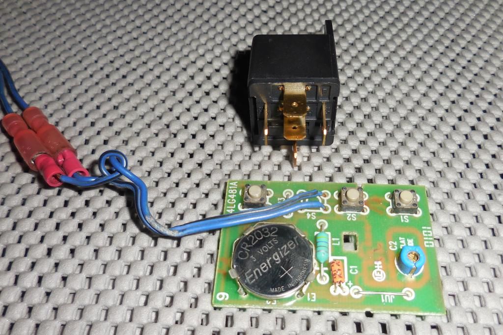
This photo might help.. I made a hole in the remote case for the wires so it can be buttoned up normally.
I believe the two horizontal prongs (IE: Left and Right in the photo) are for the "signal" 12v. and 2 of the vertical prongs are the "switched" pair to complete a circuit..