-

-
I think that if you hook 2 wires to the brake power wire (make a "Y"), add a diode to each of those new wires, and then attach 1 wire to each blinker circuit it might work.
ie;
Each blinker would receive power when one of the blinkers is selected.
But the blinker power could not cross feed/supply power to the opposite side because of the diode.
(and) Both blinker filaments would receive power when the brake is applied.
{thoughts???}
Ride safe, Ted
-
-
Ted, that would work. The problem is that I also want the blinker to work while the brakes are applied. And that's more complicated than a simple diode setup. That's beyond my electronics abilities to make that work with individual components. I have another controller, powered, that should be here today. We'll see how that goes.
-
-
I did it! The powered light controller worked!!! The only change I made to the wiring is the +12v for the controller is sourced from the running light feed. I did that so there would be no chance of parasitic draw.
https://www.amazon.com/gp/aw/d/B08N68MNSL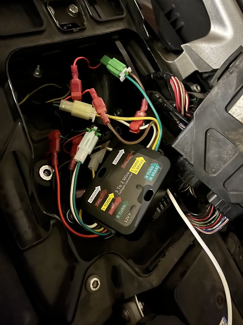
Click for brief video
-
-
Congrats. The only thing you didn't show in the video was turn signal on, then brake at same time. Which was kinda the whole point, right?

-
-
You are correct. I did not. Here it is.

-
-
You are correct. I did not. Here it is.
Looks good!
-
-
Thank you. I am extremely happy with the final result. I'm glad I kept at it. The last lighting module almost beat me. It was difficult to find all the right plugs and sockets. Manufacturers don’t want you to know who they use for basic connectors.
-
-
To consolidate items in one post, here's a list of most everything you'd need. Checked for correctness 11/22/22. Links still valid as of that date.
No mod lights:
City lights: https://www.amazon.com/gp/product/B0186P1MUW/
Headlights: https://www.amazon.com/dp/B07TQLK6SH/
Turn Signals: https://www.amazon.com/dp/B08DHMNDF2/
To do switchback lighting:
Front Switchbacks white/amber: https://www.amazon.com/gp/product/B09C234Y12
Turn signal sockets to accept 1157 bulbs: https://www.amazon.com/gp/product/B096RPQ4MP
Rear red 1157 bulbs: https://amazon.com/dp/product/B08H4MXQMZ/
OEM style Kawasaki connectors: https://amazon.com/dp/B07FCLGF3T
Trailer lighting controller: https://www.amazon.com/gp/aw/d/B08N68MNSL
-
-
Figured it was about time for an update. I'm about halfway through my second Phoenix summer with the LED headlights and city lights. I am happy to report that they are still fully functional. I ride at least 40 miles a day. Commute 5 days a week, and one longish weekend ride. Switchbacks are also still working, but they were installed just prior to this summer. 4 months though, and they are also still going strong.